Case study
Computational Fluid Dynamics (CFD) methods in barrier technology.
-
Reading time 15 min
-
A study by
IMA Life
Introduction
Among the many challenges encountered in the design and qualification of barrier systems, necessary to achieve and maintain aseptic conditions in fill-finish lines or in stand- alone systems such as isolators for material transfer, dispensing and sterility testing, the management of air or fluid dynamics inside the systems plays a key role. In this regard, the use of Computational Fluid Dynamics (CFD) methods is viewed as a valuable and often fundamental asset both in terms of Quality By Design, i.e. as direct support for the design of classified areas and integrated machines, and as a risk analysis and validation support method through smoke studies. In this feature we will show the different computational options within the scope of CFD calculation methods with practical cases.
Background
Computational Fluid Dynamics (CFD) calculation methods use complex mathematical equations to simulate the behaviour of fluids in usually three-dimensional environments. Real 3D models of a machine or plant are used as starting points for the simulations. The equations describe the fundamental laws of fluid dynamics, such as the conservation of mass, momentum, and energy.
To resolve them, the fluid domain is divided into a three-dimensional grid of smaller elements called cells or control volumes (Figure 1). Some of the complexity of the study often lies in this phase, which requires specific expertise to evaluate the right sizing of the grid, avoiding a loss of resolution and the risk of obtaining an unrealistic model, or of having too many items in the mesh and not being able to manage the model computationally (which would require too much time and computing power).
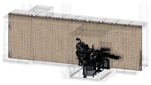
Figure 1: example of calculation grid.
The equations are numerically approximated and solved iteratively to calculate fluid properties such as velocity, pressure, and temperature. This process provides a detailed digital representation of the fluid flow in the simulated environment, allowing engineers to analyse and optimise the design of systems or devices. CFD simulations allow any critical issues to be anticipated in the isolator design; these could be identified through the use of smoke studies – as long as system construction has been completed.
Specialisation and cooperation
IMA Life relies on a team of professionals specialised in the modelling and creation of CFD simulations, but to be able to rise to such a complex challenge, a partnership and technical synergism has been started with HPE, an HPE Group company specialised in the development of engineering solutions, projects and products for the automotive, marine and defense industries with applications in the automation field, too. The possibility of combining IMA LIFE’s solutions, designed to meet the aseptic requirements of the pharmaceutical world, with HPE’s expertise in the world of advanced aerodynamics was a key factor in securing the capacity, know-how and also the computing power needed to be up to the new standards, beginning with GMP Annex 1, applicable since August 2023, and the ever-increasing demand for innovation, flexibility and performance of aseptic fill-finish machines.
Within the scope of IMA Life, CFD is used to support design efforts and solve a number of issues. Depending on the type of analysis required, the simulation aspects and the mathematical approach used to solve a model may change. In fact, CFD calculation methods allow for different computational options and methods. Thanks to the partnership with HPE, these methods have all been successfully applied to several case studies for the development of new machines and ongoing projects. In situations where the application of a particular method required the use of massive computing power, HPE took full advantage of the cloud-based systems available, which have superior characteristics and are up to very high performance standards, compatible with those used to perform simulations in car racing and aerodynamic simulations for applications in the defence sector.
In particular, HPE has made a calculation cluster available to the simulation department with the following characteristics: HPC ≈1000 Core Intel Xeon and a RAM memory larger than 1TB DDR4 which allows users to work on very complex models in computational terms in an efficient manner. As a storage platform, the calculation cluster in HPE has a set of high performance disks that work to guarantee both storage space (storage area where data and calculation files are stored) and high data transfer speeds (High Performance Parallel System).
The challenges of isolation technology
Within the scope of IMA Life, CFD is used to support design efforts and solve a number of issues. Depending on the type of analysis required, the simulation aspects and the mathematical approach used to solve a model may change. Various computational options are possible within the scope of CFD calculation methods.
Stationary type analysis
Given the boundary conditions, the CFD model determines the steady state that fulfils such conditions. This type of analysis focuses on constant flow conditions over time, ideal for situations where there are no significant flow changes over the course of the simulation, during the physical time of the simulated condition.
This method is one of the most widely used to study these isolation aspects, and it is preferred, whenever possible, to a non-stationary analysis which involves a greater computational weight.
Examples
- Study of the dynamics of the air flow in Grade A areas or areas protected by Grade A Air Supply (GAAS) to evaluate the correct uniformity, speed and absence of local turbulent conditions or risk of particulate dispersion (Figure 2).
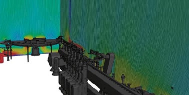
Figure 2: unidirectional flow study on a filler integrated into an aseptic isolator.
- Risk analysis on first air, i.e. evaluating the impact of components or machine parts that are located near critical areas, such as open primary containers or parts in direct or indirect contact which could impact the quality of the unidirectional flow protecting the area (Figure 3).
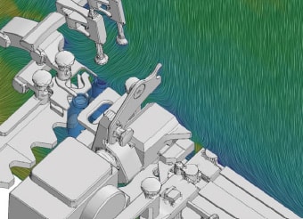
Figure 3: study of unidirectional flow on a capping machine.
- Analysis of pressure drops on ventilation ducts, circulation systems (both in C-RABS, single wall or double wall isolators) and back-up HVAC units (Figure 4).
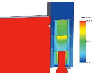
Figure 4: pressure field detected in a section of a re-intake duct equipped with a filtration system.
- Analysis of the dynamics of rotary systems. These are stationary studies supported by methods such as the “moving reference frame” capable of simulating a ventilator or rotating systems. This approach allows the dynamics of the motors inside isolators to be studied, usually in confined spaces where there is a risk of heavy turbulence or cavitation effects capable of affecting the efficiency of the motor and the dynamics of the outlet flow (Figure 5).
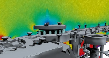
Figure 5: study of unidirectional flow on a capping station caused to rotate.
Non-stationary type analysis
A non-stationary, or transient, CFD analysis considers the change in fluid flow within a system over time. This type of analysis is useful when flow changes over time, such as in start, stop, or quick pressure transition situations. Solving the model in a non-stationary way allows transient phenomena and variations in fluid behaviour over time to be captured, offering a more complete and detailed view of the flow dynamics.
Example
- Dynamics of the pressure trend in ventilation transients. Analysis of the way in which pressure fluctuations affect the system when the isolator goes through transitional phases such as an HVAC unit reaching steady state, a machine phase change or transition from decontamination to aeration during the VHP cycle.
Multi-fluid type analysis
A multi-fluid approach CFD analysis is an advanced method that considers the interaction between two or more fluids within a system. This approach is fundamentally important to study phenomena such as the mixing of different gases inside an isolator.
Examples
- Analysis of the distribution of vapour phase hydrogen peroxide (VPHP) both during the injection phases, to check for quick and homogeneous distribution of the decontaminating gas, and during the aeration phases to optimise cycle times (Figure 6) and minimise the risk of local build-up of VPHP (Figure 7).
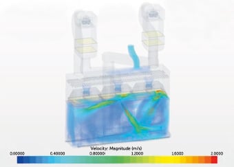
Figure 6: 3D frame of a non-stationary study simulating a phase of the decontamination cycle.
Figure 7: 2D frame highlighting the percentage content of VHP inside an isolated booth (non-stationary study).
- Analysis of the effectiveness of nitrogen inerting systems, used to prevent oxygen from reaching the head spaces created inside bottles and syringes during filling and capping. Critically important to ensure that under-isolator or RABS filling machines can preserve oxygen-sensitive drugs while ensuring the lowest possible residual oxygen content.
Thermal type analysis
A CFD analysis using a thermal approach focuses on simulating and understanding heat transfer phenomena within a fluid system. This approach is essential for evaluating the temperature distribution and variation within devices or environments of interest. Solving the model using a thermal approach involves implementing energy
conservation equations, which take into account the mechanisms of thermal radiation, conduction and convection.
Examples
- Analysis of heat exchange in the isolator: simulation designed to determine the temperature distribution in the air flows, the heat exchange with the isolator walls and the convective motions that are generated in critical interfaces such as CIP/SIP systems during sterilisation phases (with surfaces at 121°C), dry heat phase of depyrogenation tunnels and convection and heat exchange effects between freeze-dryers and loading/unloading isolators, especially in cases of “cold loading” i.e. cold plates at the time of bottle loading (Figure 8).
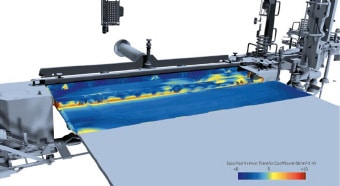
Figure 8: map of HTCs (Heat Transfer Coefficients) on the bottle transfer plate.
- The map showing the point trend of the convection coefficient, i.e. the output of the CFD study in actual operating conditions, was used as a boundary condition of an FEM analysis aimed at evaluating the deformation of a component when subjected to thermal loads (Figure 9).
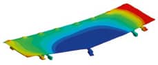
Figure 9: FEM analysis on connecting plate.
- Efficiency study and development of thermal batteries. It allows thermal batteries for air heating or cooling to be developed which can be integrated inside the isolator with, therefore, stringent space requirements.
Multi-phase analysis
A multi-phase CFD analysis, usually combined with a thermal analysis, focuses on studying flows involving multiple phases or states of matter, such as liquid-gas, liquid-solid, or gas-solid. This approach considers the interactions and dynamics between different phases, allowing complex phenomena to be explained, e.g. the suspension of particles in a fluid, the separation of phases in a mixture or the evaporation of a liquid.
Examples
- Analysis of condensation risks carried out on filling circuits located inside isolators or RABS in which a unidirectional flow can be observed at given temperatures and humidity values. Calculation of the dynamic cooling effects of air in motion and risk of condensation on cold surfaces (Figure 10).

Figure 10: temperature field around the filling circuit of a cold pharmaceutical product .
- Analysis of the build-up of ice and condensation on freeze-dryer plates during loading phases in cold loading conditions, in which the freeze-dryer plates can be adjusted to values close to zero (4-6 °C) or even to freezing temperatures (-40 / -50 °C).
Non-stationary analysis with time-varying geometry
These are extremely challenging simulations, which reflect the state-of-the-art of CFD modelling today. Simulating involves not only air dynamics in a time-varying scenario, but also mixing machine dynamics – and therefore, changes in the physical model – with fluid equations. In other words, the CFD simulation is performed on a machine that while moving according to its own cyclical pattern has an impact on the air – and this in turn responds to its specific boundary conditions. This type of model causes a continuous variation of the mesh and therefore requires extreme computing power, allowing, however, to determine when the movement of a mechanical part, such as a robotic arm, can trigger turbulence or disturbances in the unidirectional air flow which would not be visible otherwise.
Conclusions
CFD methods are used to support design phases and can be produced as documentary evidence attached to executive projects, objectively demonstrating the quality-by-design approach that is mandatory in aseptic studies. They are the first stage of airflow visualisation studies required by the new GMP Annex 1 and a tool that can guide and improve the validation phases through smoke studies in filling plants.
Examples of case studies
Verification of unidirectionality and speed of the air flow:
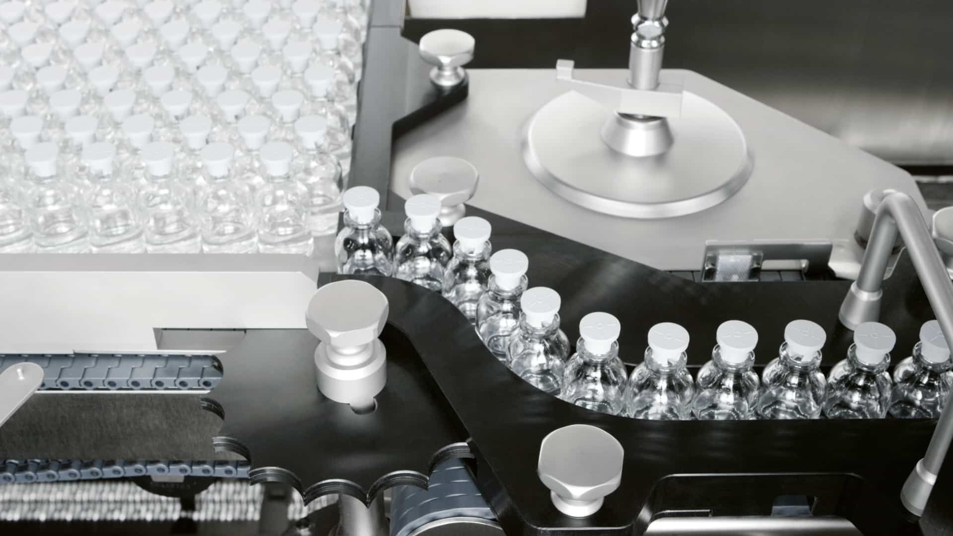
Purpose: To verify the correct distribution of the air flow of an Xtrema bottle filler inside an isolator. The objective was to prove that there was no turbulence or risk of contamination at critical points and that the air speed was adequate to meet GMP requirements.
To do this, the steady-state analysis method was applied using the real 3D model of the machine and isolator.
Result obtained: CFD demonstrated that the unidirectional flow distribution was adequate, there were no critical turbulences and the air speed was within the range 0.45 m/s +/- 20% at the different points where the unidirectional flow will be qualified. The document obtained was viewed by the customer during the design review and became part of the system validation file (Figure 11).
Figure 11: unidirectional flow study on Xtrema filler.
Verification and optimisation of first air impact
Purpose: a robot gripper of the Injecta filler was placed over a nest grip point taken from an RTU container during the pick & place transient phase. The intention was to evaluate whether the design of the gripper could be improved to prevent first air from being affected during this transfer phase. The intention was also to check the correct unidirectionality of the air in the filling area next to the robotic drives.
The method used was steady-state analysis using the real 3D model of the machine and isolator.
Result obtained: CFD allowed us to optimise the 3D model in order to reduce the impact of the gripper geometry on the air which then skimmed along the primary container, ensuring better compliance with the first air principle. The trajectories of the anthropomorphic robots were optimised to minimise the risk of impact on first air (Figures 12 and 13).
Figure 12: unidirectional flow study on Injecta 36.
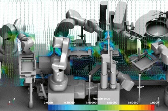
Figure 13: unidirectional flow study on Injecta 36.
VPHP containment in the Nebula tunnel
Purpose: The Nebula system uses a high concentration of VPHP which is kept inside an open tunnel, provided, however, with aerodynamic protection so that VPHP cannot leak out of the Nebula decontamination chamber. The study of the pressure cascade and of the protective flows therefore had to demonstrate that the VPHP is kept at a specific point within the system – preventing it being let into neighbouring chambers.
The method used was multi-fluid analysis.
Result obtained: thanks to multi-fluid simulation, in which the distribution of two fluids, namely air and VPHP, is calculated, the design of Nebula was optimised so that the VPHP flow (in red) remained confined inside of the decontamination chamber in all different operating conditions (Figures 14, 15 and 16).
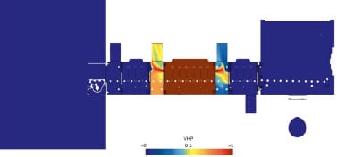
Figure 14: concentration of VPHP along the centerline section of Nebula.
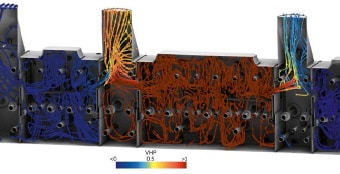
Figure 15: streamlines simulating the turbulent dynamics of VPHP at high concentrations.
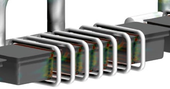
Figure 16: outlet motion from the Nebula nozzles and related impact on the passing tubs.
Impact analysis of parts moving at high speed on first air
Purpose: to evaluate whether the high-speed dynamics of the cap pick & place system on a new Injecta 36 capable of filling and capping 36,000 containers per hour could cause a problem with unidirectionality and first air in the critical filling area.
The method used was non-stationary analysis with time-varying geometry.
Result obtained: the simulation demonstrated how the turbulence triggered by the mechanical part movement was unable to affect first air in the capping area.
Conclusions
CFD methods have been applied to find innovative solutions or improve the design of isolators and RABS, but also to improve traditional or robotic filling machines, process systems such as freeze-dryers, decontaminating tunnels or special solutions such as the new Nebula decontaminating system.
During the IMA Life experience, some factors within CFD were found to be decisive. First of all, the creation of an internal team specialised in CFD simulations – capable of quickly determining the appropriate simulation model and evaluating how to set parameters and boundary conditions.
Being able to count on the support of industry specialists such as HPE Group in close cooperation with our internal team has allowed us to quickly set up complex simulations, support the cleaning of 3D models and obtain massive computing power. Last but not least, the expansion of models towards increasingly complex scenarios where the presence of thermal dynamics, mixed fluids, phase change and time-varying 3D models are an achievable and realistic possibility at computational level.